
4 Knowledge Representation in Pure Prolog
Solutions
4.1 Means of Transport
Represent the following "world" in Prolog:
- Public transport: bus, train, airplane, ship.
Private transport: bicycle, motorcycle, car. - Vehicle: bicycle, motorcycle, car, bus.
- Motor vehicle: vehicle with a motor.
- Bicycle: slow, eco-friendly.
- Car: fast, dangerous, has a petrol engine.
- Bus: rather fast, has a petrol engine.
- Train: fast, has an electric motor.
- Airplane: very fast, has a petrol engine.
- Ship: slow, has a diesel engine.
- Vehicles with a petrol engine are eco-hostile.
- Vehicles with an electric motor are eco-friendly.
- Public transport is safe.
Replenish the "knowledge base" such that the following questions can be answered "correctly" and "completely":
- Which transport means are fast, which are eco-friendly, which are safe?
- Is the airplane fast? How fast?
- Which means of transport have a motor?
Can your database answer the following question?:
- Which properties has the car?
If not, how should the database be modified to answer this question?
Solution 4.1
4.2 Problems with Insulators
Express the following knowledge in Prolog:
Power transmission lines are attached to poles using insulators. Breakdowns of insulators can arise in one of three ways:
- A flashover arc is a breakdown and conduction of the air around the insulator, causing an arc along the outside of the insulator. The flashover arc happens when the voltage is too high, e.g. because of a lightning strike.
- A puncture arc is a breakdown and conduction of the material of the insulator, causing an electric arc through the interior of the insulator. The puncture arc happens when the insulator material is faulty or has cracks. The insulator is damaged and must be replaced.
- A surface leakage is an undesirable flow of current over the surface of the insulator. It happens when the surface is dirty and wet. Composite polymer materials are prone to the surface leakage. When creepage pathes are built the insulators must be replaced.
The following queries should be supported:
- Which are the possibilities for a insulator breakdown?
- What are the possible causes and consequences?
Solution 4.2
4.3 Resistor Network (Representation by Terms)
A resistor network, in which the resistors are connected in series or in parallel, can be described by a compound term. For example:
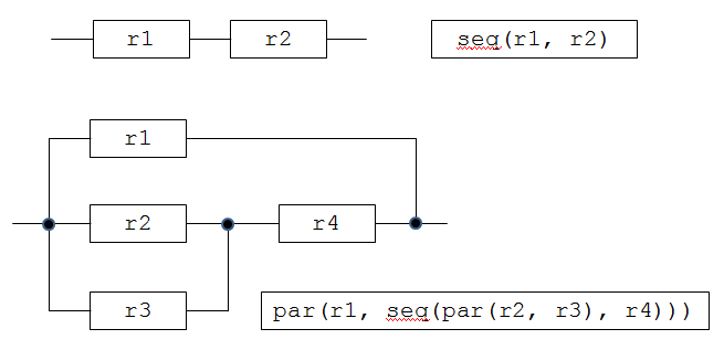
Fig. 4.1: A Resistor Network
A resistor can be specified by the fact resistor( R, V), where V is the resistance of the resistor R measured in Ohm, e.g. resistor( r1, 5). Define the predicate
res( N, R)
/* R is the resistance of the network N. */
Solution 4.3
4.4 Digital Circuits (Representation by Clauses)
Represent the following circuit "adder1" in Prolog:

Fig. 4.2: Digital Circuit "Adder1"
Hint:
adder1( In1, In2, Cin, Out, Cout) :-
    xor( In1, In2, A), xor( A, Cin, Out),
    ... .
Simulate the circuit and check that this is a 1-bit full-adder, i.e.
Out = (In1 + In2 + Cin) mod 2
Cout = (In1 + In2 + Cin) div 2.
Use this 1-bit full-adder to implement a N-bit full-adder with overflow:
adder_overflow( X, Y, Z, OF).
X, Y, Z are lists with N bits starting with the "most significant bit", Z is the sum of X und Y, and OF is the overflow.
Finally implement the N-bit full-adder:
adder( X, Y, Sum).
where Sum is the sum of X und Y. It is a list with N+1 bits starting with the "most significant bit".